
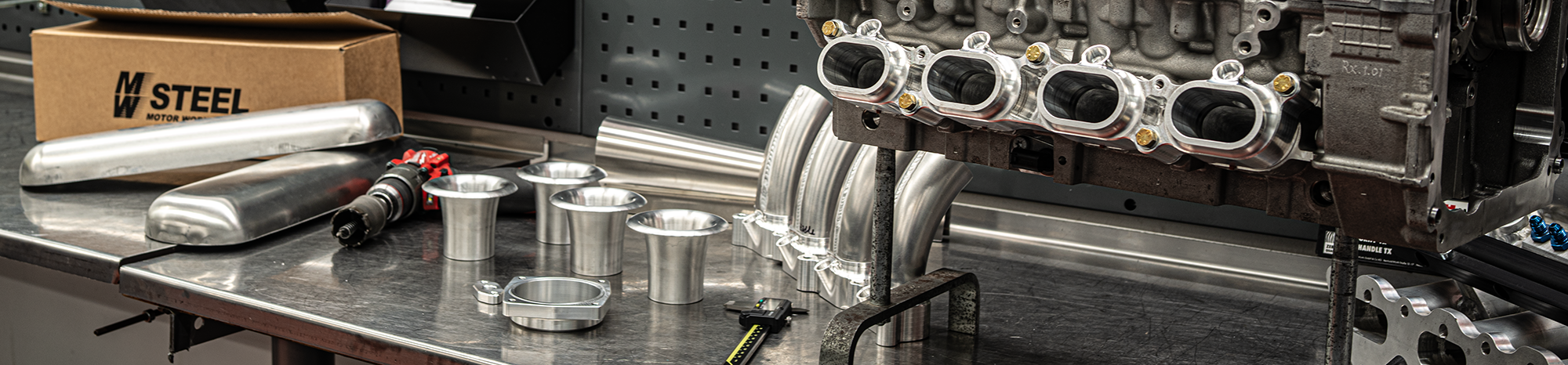


More than 3,000 Dual Plenum intake manifolds and fabrication kits have been supplied worldwide over the history of the product line.
Now developed and offered under the MWS Motorsport brand, the range continues to evolve with new engine applications, updated components and ongoing technical development. Dual Plenum solutions are designed and manufactured in Finland.
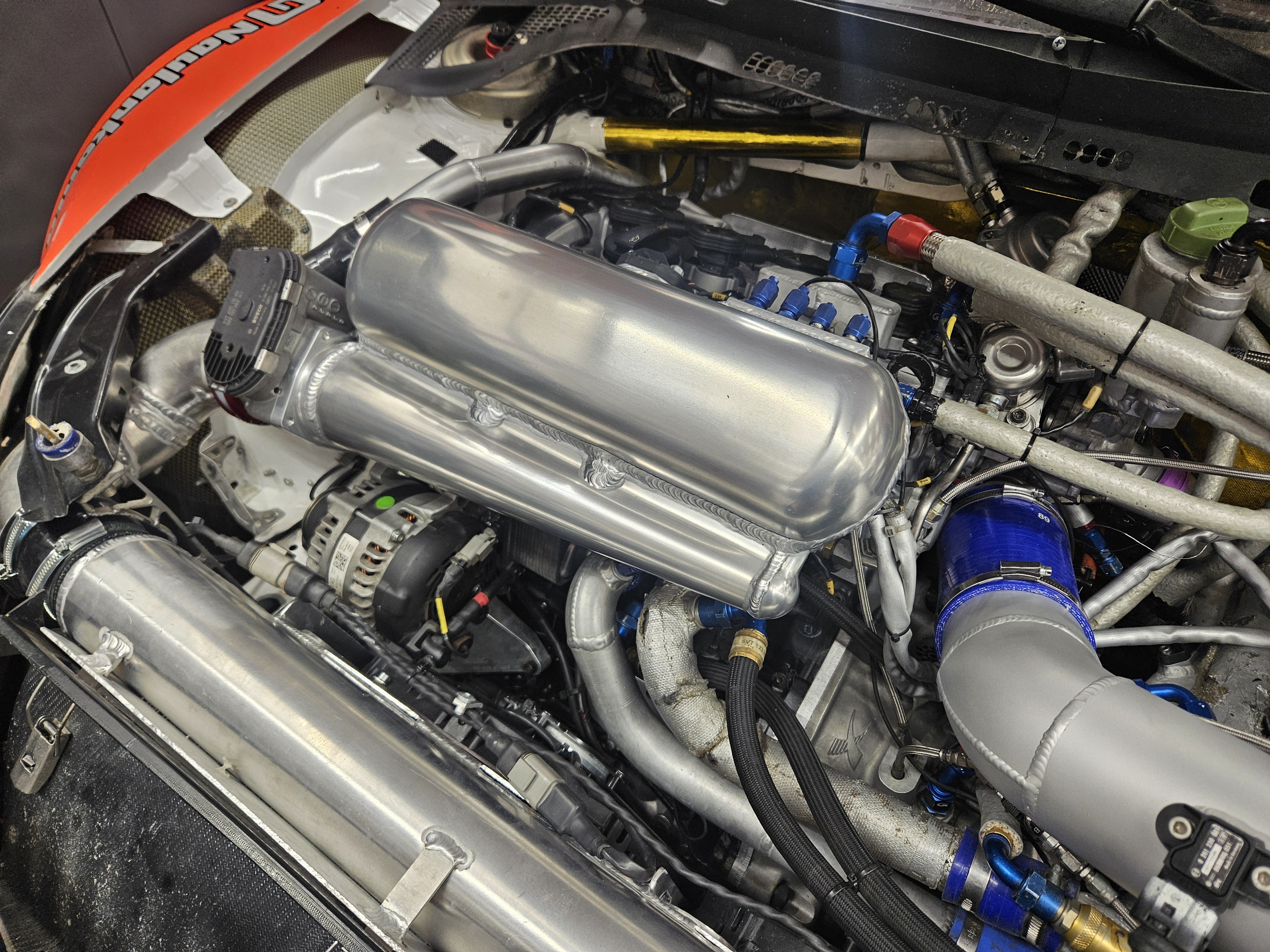
MWS Motorsport Dual Plenum intake manifold – controlled airflow for high-output engines
As engine power and boost pressure increase, the intake manifold becomes increasingly important. Its role is not simply to carry air from the throttle body to the cylinders, but to distribute airflow as evenly as possible to each cylinder.
MWS Motorsport Dual Plenum intake manifolds are designed specifically for high-output turbocharged and competition engines, where high flow capacity, even air distribution and a well-matched overall design are important.
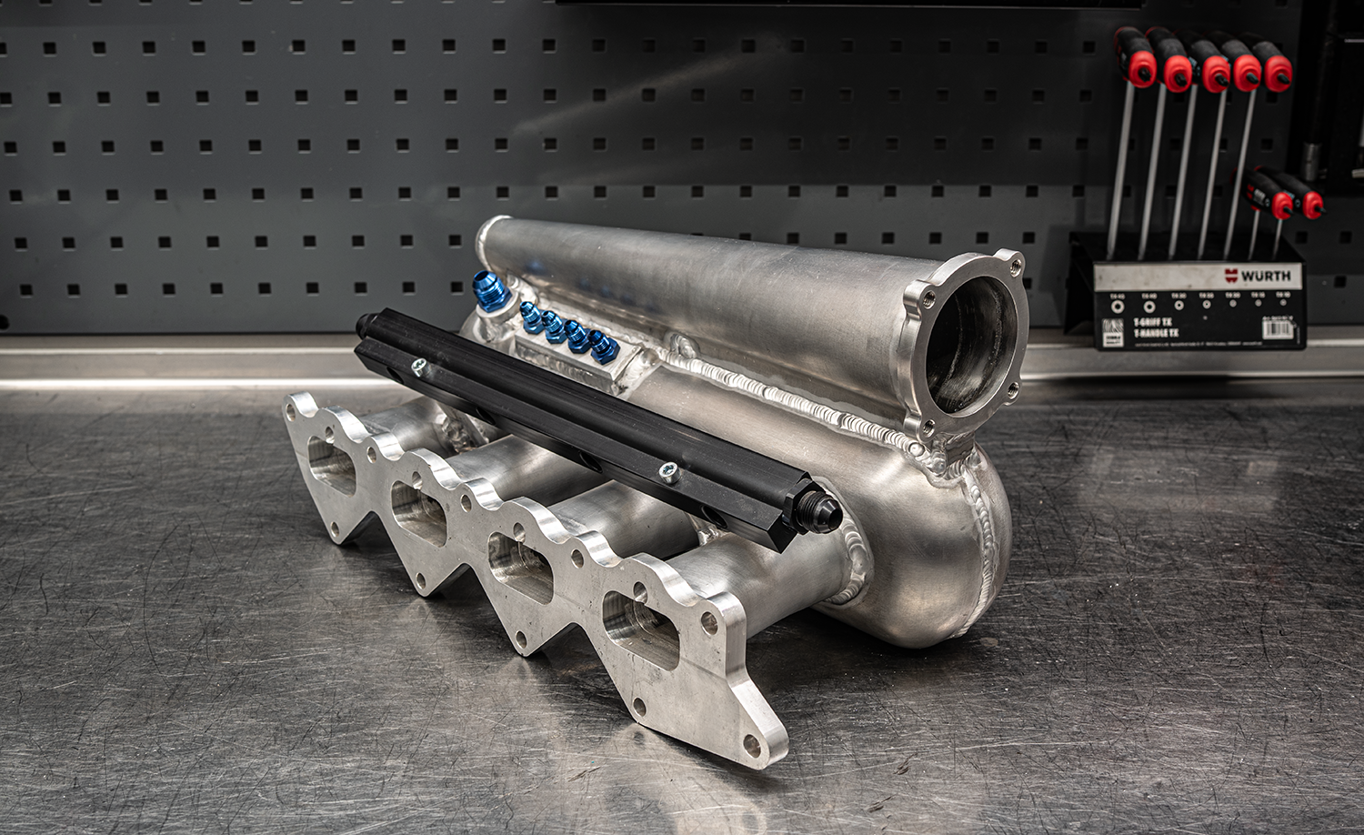
What is a Dual Plenum intake manifold?
In a conventional intake manifold, air from the throttle body enters a common plenum before being distributed to the individual intake runners.
A Dual Plenum design manages airflow through two plenum chambers. Air from the throttle body enters the first, or primary, plenum and is then directed through a controlled flow path into the secondary plenum connected to the runners.
The aim is to balance air pressure and flow before the air is distributed to the individual runners. This can reduce uneven air distribution caused by throttle body position and high air velocity.
This is particularly relevant in high-output turbocharged engines, where the volume of air passing through the intake manifold is considerably greater than in the original application.
Bernoulli’s principle in a Dual Plenum design
The operation of the tapered primary plenum in an MWS Motorsport Dual Plenum intake manifold can be partly illustrated using Bernoulli’s principle.
In simplified terms, Bernoulli’s principle states that static pressure decreases as flow velocity increases. As the flow slows down, some of its kinetic energy can be converted back into static pressure.
In a Dual Plenum design, the cross-sectional area of the primary plenum and the flow path between the primary and secondary chambers influence how air velocity and pressure are distributed inside the manifold.
The aim is to achieve as even an air distribution as possible in the secondary plenum and, in turn, at the runners.
However, intake flow in a running engine is pulsating and involves pressure waves, turbulence and flow losses. Bernoulli’s principle therefore describes one of the fluid mechanics principles involved, rather than the complete behaviour of the intake manifold.
Why does even air distribution matter?
Although an engine is considered as a complete system, each cylinder has its own combustion chamber.
If the intake manifold distributes air unevenly, the cylinder filling can differ from one cylinder to another. These differences become more significant at high power levels and boost pressures.
A well-designed intake manifold aims to provide pressure and flow conditions that are as similar as possible at each runner.
More even cylinder filling helps keep differences between individual cylinders to a minimum.
Shaping the runner inlet
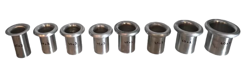
Airflow from the plenum into a runner also depends on the shape of the runner inlet. A sharp edge can cause flow separation and additional flow losses.
The rounded entry of a velocity stack helps guide air into the runner more smoothly. Inside the plenum, its purpose is to shape the runner inlet, not to increase manifold volume.
Complete manifold or fabrication kit?
A complete engine-specific intake manifold reduces fabrication work: there is no need to assemble and weld the plenum and runners from separate components. Any additional parts needed for installation must still be checked for the specific product.
A fabrication kit or individually selected components offers more freedom to fit the manifold into the engine bay. This approach suits projects where, for example, throttle body position or runner layout requires a custom design.
Fabrication requires fitting the components, welding with a process suitable for aluminium and checking the completed assembly for leaks.
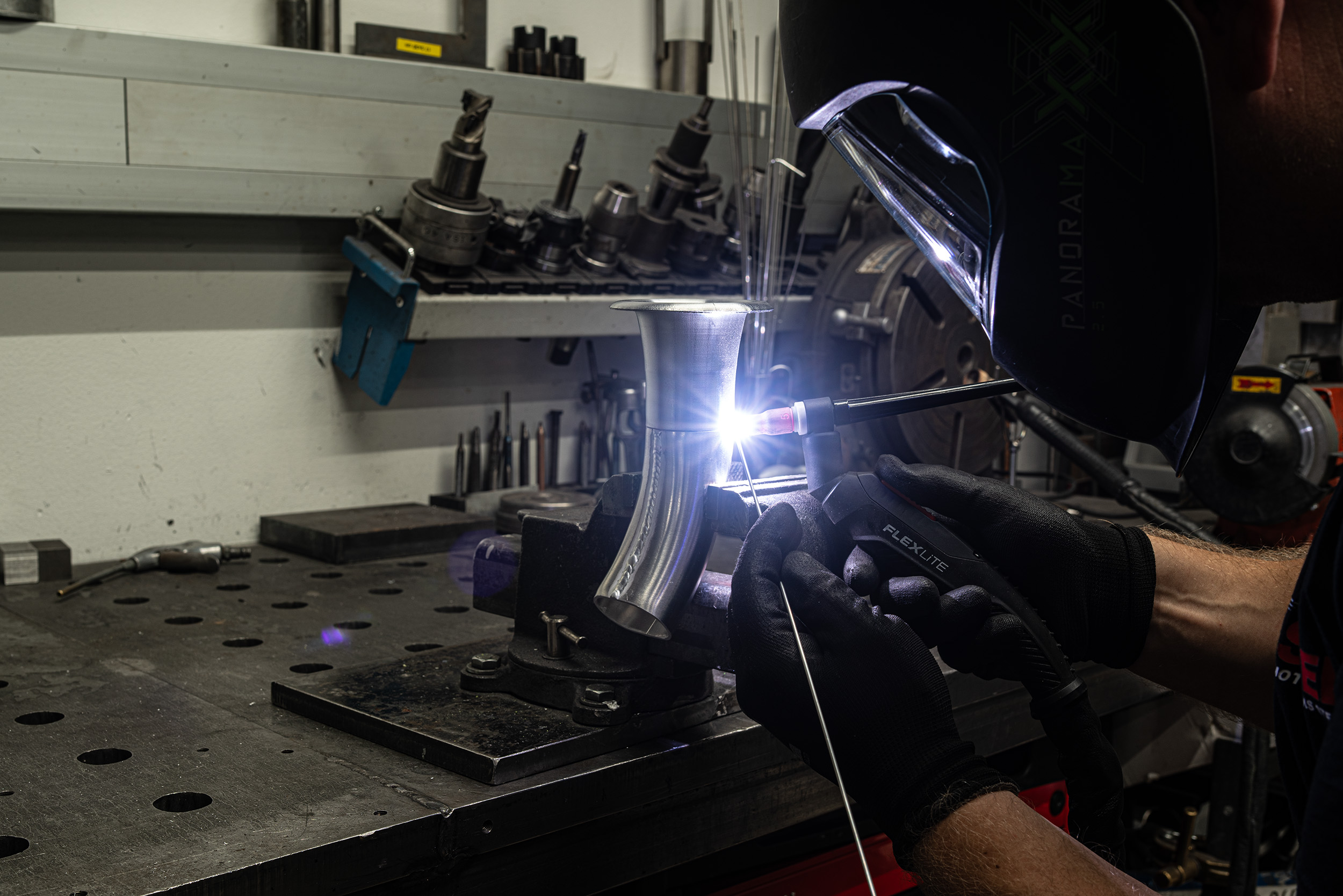
The runner-to-velocity-stack joint is welded using a process suitable for aluminium.
Designing the intake manifold as a complete system
A large plenum, throttle body or set of runners does not automatically produce a better-performing intake manifold. Sizing must take account of engine displacement, the intended operating speed and power range, forced induction and the overall intake system.
The requirements of a high-revving competition engine can differ from those of a road car that prioritises response and a broad operating range. The intake manifold should therefore be considered as part of the engine’s breathing system, rather than as an isolated performance component.
From component selection to a complete assembly
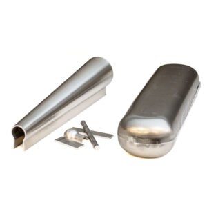
Which parts does your engine need, and what is included in a fabrication kit? Our separate selection guide covers flanges, runners, velocity stacks, the throttle body, and sensor and hose connections, with engine-specific examples.
Dual Plenum intake manifold selection guide — coming soon.
Summary
A Dual Plenum design aims to manage airflow inside the manifold before it is distributed to the cylinders. The result nevertheless depends on the sizing of the complete intake manifold and how it is matched to the engine. Choose an approach that suits the project’s requirements and the fabrication resources available.
Complete intake manifolds
Engine-specific MWS Motorsport Dual Plenum intake manifolds.
View intake manifolds →
Intake manifold fabrication kits
Build a Dual Plenum intake manifold to suit your project.
View fabrication kits →
Intake manifold components
Flanges, runners, velocity stacks and other fabrication components.
View intake manifold components →